This site uses cookies to provide you with a great user experience and to show you relevant ads. If you’re OK with that, just continue. To find out more, please review our privacy policy.
This is a blog to help diagnose ignition faults which result in no spark on 50cc Yamaha Aerox mopeds.
This blog applies only to the later Aerox CDI's as fitted to all Yamaha Aerox 50cc from 2004.
The later Aerox CDI looks completely different to the earlier CDI and can be easily identified from the picture below.
It's assumed you have and know how to work a multimeter!
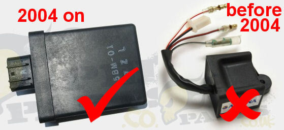
This blog only applies if your CDI is the same as the one on the left in the above picture!
How to test for a spark
As a general rule of thumb, in order for there to be a satisfactory ignition spark the spark should be able to consistently jump a gap of minimum 6-7mm when tested in open air. It is not enough just to see the spark plug sparking when it is away from the cylinder, it has to be able to jump this distance gap otherwise it is unlikely to fire efficiently and consistently when fitted and under pressure in the combustion chamber.
The easiest way to check the spark gap is with a spark gap tester like this one.
There are some alternative methods and further reading on this at the beginning of this blog here.
Description
Unlike earlier Yamaha Aerox mopeds and most other mopeds, the later Aerox CDI's are powered by a DC voltage from the battery. Most moped CDI's are powered by an AC voltage generated by a separate dedicated coil on the stator but this is not the case for the later Aerox. On the later Aerox the stator itself is therefore not involved in the ignition (spark) system apart from the pickup unit as shown in the picture below.
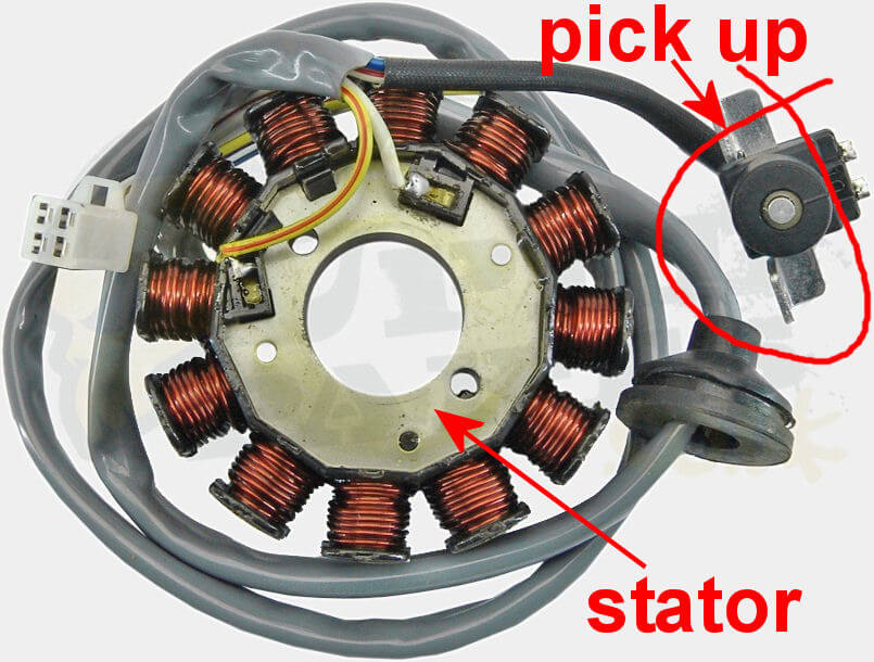
This pickup unit can be found underneath the waterpump cover next to the flywheel. As the flywheel spins there is a rasied 'nobble' on the flywheel which passes the pickup every revolution creating a small impulse in the pickup as it passes which helps tell the CDI when to fire the spark.
Before testing in any further detail it is important to first remove the waterpump cover and check that this pickup has not come loose and that the air gap between pickup and the raised nobble on the flywheel (when it passes the pickup) is very close to 1mm.
It is also necessary to check the battery is fully charged and showing in excess of 12 volts when tested with your multimeter.
Testing
The Aerox CDI is located on the left side of the seat as shown on the following photo. Firstly remove seat and panels as necessary to access it.
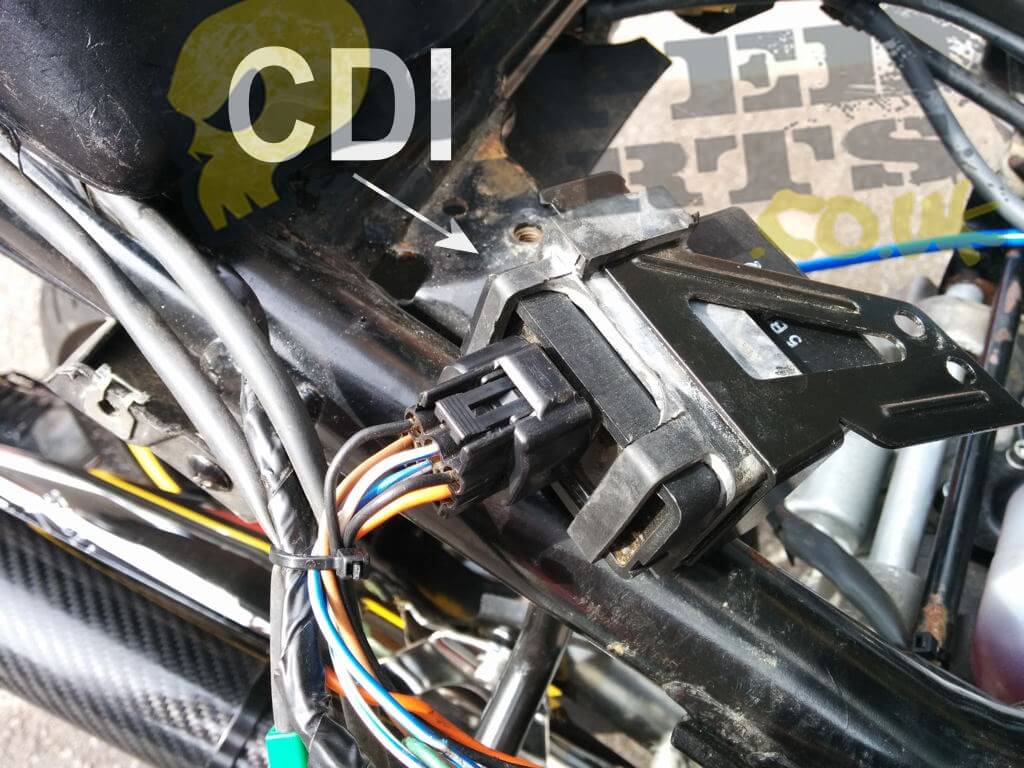
Once located and exposed, unplug the CDI and place it aside. Testing is done from the open pins on the CDI connector block left exposed after the CDI has been removed.
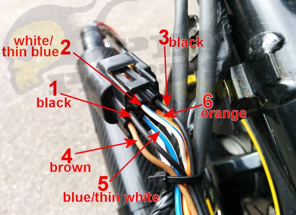
This should leave you with the connector block as shown in the below photo. For clarity and ease of reference we have numbered the wires.
Firstly both of the black wires (1 and 3) should be connected to earth. This can be tested by checking for continuity between one of the black wires and the bike frame and/ or negative battery terminal. The ignition switch does not have to be on. To do this set your multimeter to it's lowest ohm setting and check the resistance between a black wire and earth. It should be 0 ohms. A better test which additionally checks that the connection is not breaking down under load is to connect a 12 volt bulb (using wire) between the positive battery terminal and the black wire to ensure it lights brightly. Repeat this with the other black wire.
If there is not a good earth connection to both black pins follow the wiring carefully to see where it has failed. It is ok to temporarily substitute an earth directly from the battery negative terminal to the black wires for testing purposes if necessary.
Testing the pickup unit: The main wire from the pickup goes to pin 2 (white with thin blue stripe). There should be somewhere around 250 to 300 ohms resistance between this pin and either of the black pins. If you are getting this reading there is unlikely to be anything wrong with the pickup unit. If you do not get this reading follow the wires coming from the stator and pickup assembly from where they come out of the engine by the waterpump cover. After approximately 12 inches they terminate in a small connector block with 4 wires. Disconnect this block and test the stator wires here directly from the stator/pickup unit. The 2 wires to test are the white wire with a thin blue stripe and the red/white wire. The red/white wire is actually connected directly into the black wires (earth) further along the loom. If you are getting the correct resistance here but not at the CDI plug then there is a problem with the wiring between these 2 points and it should be easy to follow it through and see what is wrong.
If you are still not getting a reading near the 250-300 ohm range then there is a problem with the pickup unit. The pickup unit is only available to buy complete with the stator assembly.
Power source: There should be +12 volts present at the brown pin (pin 4) when the ignition is switched on. Check with a multimeter between pin 4 and earth. It's also a good idea to check that this supply isn't breaking down under load by connecting a 12v bulb between the brown pin and battery earth (negative) to ensure the bulb lights brightly.
If there is not 12 volts present check the battery fuse and trace the wire back manually to the ignition switch if necessary to see where the supply stops.
If everything tests ok so far this just leaves the coil wire which is pin 6 (orange) and runs directly to the coil which is located underneath the right hand footplate at the back.
It's quite difficult to test this output without an oscilloscope because the spark signal to the coil is a very brief but fairly high (approx 100 volt) 'impulse' of extremely short duration. Depending on your multimeter you may pick up a small voltage (e.g. up to 8 volts) if you set it to AC but this isn't a reliable test. Check for continuity between both ends of the orange wire (pin 6) and where it connects to the coil (disconnect it from the coil to test). You should have 0 ohms showing the wire is not broken. There also should be no continuity (infinite resistance) between the orange wire and earth showing it is not shorting anywhere it shouldn't be to another wire or the frame. Check also that the coil is still earthed and bolted to the frame properly
At this stage all potential faults should have been eliminated which only leaves either the CDI or the coil as the cause of the fault.
It is difficult to test the coil without a coil tester or swapping with a known working one so as a general rule at this stage replace the coil first if you are seeing an AC voltage above 2 volts AC between the orange pin 6 wire and earth when cranking the engine (beware this is actually over 100 volts!) and replace the CDI first if you are seeing no voltage here.
It's actually quite easy to make a coil tester but the parts are a little more than the cost of a new coil (currently £10.25) so unless you are doing a lot of diagnostic work it is cheaper just to try a new coil.
It's worth noting that the starter will not operate with the CDI unplugged unless you connect pin 5 to earth (this pin takes an earth directly to the starter relay only when the CDI is plugged in).